Stewart Platform
Goal
Using this project as a way of becoming familiar with zephyr and the nrf5340 by using PWM signals to make a functional stewart platform
Production
Tools
6 servo motors
nrf5340 dev-kit
Setting up devices
| Signal | Channel | Label | Pin |
|---|---|---|---|
| &pwm0 | 0 | pwm_alpha | 1.4 |
| &pwm0 | 1 | pwm_beta | 1.5 |
| &pwm1 | 0 | pwm_gamma | 1.6 |
| &pwm1 | 1 | pwm_delta | 1.7 |
| &pwm2 | 0 | pwm_epsilon | 1.8 |
| &pwm2 | 1 | pwm_zeta | 1.9 |
NRF5340 has 4 pwm generators each with four channels I made a overlay file and mapped 6 signals to corrospond with six servos, by using 3 generators, with 2 channels each.
{
        mypwms{
        compatible = "pwm-leds";
        pwm_alpha: pwm_alpha{
        status = "okay";
        wms = <&pwm0 0 PWM_MSEC(20) PWM_POLARITY_INVERTED>;
        };

        pwm_beta: pwm_beta{
        status = "okay";
        pwms = <&pwm0 1 PWM_MSEC(20) PWM_POLARITY_INVERTED>;
        };

        pwm_gamma: pwm_gamma{
        status = "okay";
        pwms = <&pwm1 0 PWM_MSEC(20) PWM_POLARITY_INVERTED>;
        };

        pwm_delta: pwm_delta{
        status = "okay";
        pwms = <&pwm1 1 PWM_MSEC(20) PWM_POLARITY_INVERTED>;
        };

        pwm_epsilon: pwm_epsilon{
        status = "okay";
        pwms = <&pwm2 0 PWM_MSEC(20) PWM_POLARITY_INVERTED>;
        };

        pwm_zeta: pwm_zeta{
        status = "okay";
        pwms = <&pwm2 1 PWM_MSEC(20) PWM_POLARITY_INVERTED>;
        };
        };
        }
Then I outputted each PWM signal to pins 1.4 - 1.9
&pwm0_default {
        group1 {
        psels = <NRF_PSEL(PWM_OUT0, 1, 4)>, <NRF_PSEL(PWM_OUT1, 1, 5)>;
        };
        };

        &pinctrl {
        pwm1_default: pwm1_default {
        group1 {
        psels = <NRF_PSEL(PWM_OUT0, 1, 6)>, <NRF_PSEL(PWM_OUT1, 1, 7)>;
        };
        };

        pwm2_default: pwm2_default {
        group1 {
        psels = <NRF_PSEL(PWM_OUT0, 1, 8)>, <NRF_PSEL(PWM_OUT1, 1, 9)>;
        };
        };
        };
Testing Servos
Once I had the device tree configured I went on to test each servo could run inpendantly.
The pulse width ran form 1000-2000, representing 0-90degrees.
First I organised each pwm signal into a array of servo data
typedef struct {
        const struct pwm_dt_spec name;
        uint32_t pulse;
        } servo;

        servo servos[SERVO_NUM] = {{PWM_DT_SPEC_GET(DT_ALIAS(alpha)), MINPULSE},
        {PWM_DT_SPEC_GET(DT_ALIAS(beta)), MINPULSE},
        {PWM_DT_SPEC_GET(DT_ALIAS(gamma)), MINPULSE},
        {PWM_DT_SPEC_GET(DT_ALIAS(delta)), MINPULSE},
        {PWM_DT_SPEC_GET(DT_ALIAS(epsilon)), MINPULSE},
        {PWM_DT_SPEC_GET(DT_ALIAS(zeta)), MINPULSE}};
then made a function that sets all servos to the angle. The idea being, once all calculations for the servos desired angles are done then set all the servos in one function, avoiding too much delay between servos
void set_Servos(servo *servos) {
        printk("Setting Servos");
        for (int i = 0; i < SERVO_NUM; i++) {
        pwm_set(servos[i].name.dev, servos[i].name.channel, PWM_USEC(PERIOD),
        PWM_USEC(servos[i].pulse), 0);
        }
        }
I made another function so that I could input degrees to move servos instead of pulse width
uint32_t angle_to_pulse(uint8_t angle) {
        float angle_pct = ((float)angle / 90.0f);
        uint32_t pulse = MINPULSE + (angle_pct * (MAXPULSE - MINPULSE));
        return pulse;
        }
Then in the main loop I put in two angles values for the servos to switch between
 if (servos[3].pulse == angle_to_pulse(25))
        servos[3].pulse = angle_to_pulse(50);
        else
        servos[3].pulse = angle_to_pulse(25);
once all servo pulses have been store I set the servos and waited before repeating the loop
set_Servos(servos);
        k_sleep(K_SECONDS(SLEEP_TIME_S));
Prototype
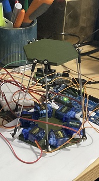
prototype with some hexagons and blue-tack
after adjusting the fit I implemented uart to test the movement, this also allows the pulse of each servo to be adusted through events as opposed to a continous loop
 if ((evt->data.rx.len) == 1) {
        switch (evt->data.rx.buf[evt->data.rx.offset]) {
        case 'w':
        for (int i = 0; i < 6; i++)
        servos[i].pulse = MIDPULSE;
        set_Servos(servos);
        break;
        case 's':
        for (int i = 0; i < 6; i += 2)
        servos[i].pulse = MINPULSE;
        for (int i = 1; i < 6; i += 2)
        servos[i].pulse = MAXPULSE;
        set_Servos(servos);
        break;
        }

Current Status
Unfortunately this project is on hiatus due to the developer board blowing up while experimenting :(